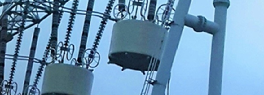
Reactor Applications
- Shunt reactors
- Thyristor-controlled reactors
- Current-limiting reactors
- Smoothing reactors
- Filter reactors
- Damping reactors
- Test reactors
- Line traps
1. Shunt Reactor:
A shunt reactor is connected in parallel to the power system. The shunt reactor compensates for capacitive VARs that exist on lightly loaded transmission lines or underground cables. This ensures that operating voltages are maintained within acceptable levels and that the system is operating efficiently.
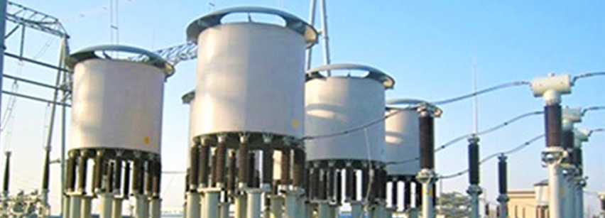
2. Thyristor controlled reactor:
A thyristor-controlled reactor [TCR] is a reactor connected in series with a bidirectional thyristor valve. The thyristor valve is phase controlled, which allows the value of delivered reactive power to be adjusted to meet varying system conditions.
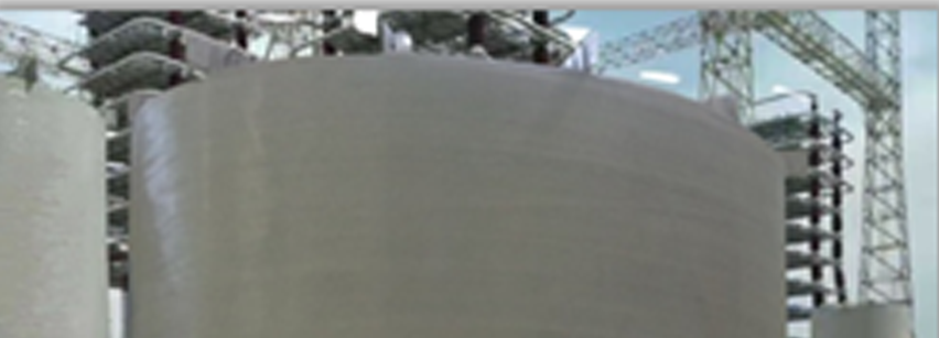
3. Current-limiting reactor:
A current limiting reactor is connected in series with the power system. It is designed to reduce short-circuit currents, which result from plant expansions and power source additions, to levels that can be adequately handled by existing transmission and distribution equipment.

4. Smoothing reactor:
A smoothing reactor is connected in series with the DC high voltage line as either part of the converter station or back to back interconnection between different transmission networks. It reduces the harmonic current [ripple], limits the inrush current during fault conditions, limits the DC phase current rate of rise and improves the dynamic stability of the power system.

5. Filter reactor:
A current limiting reactor is connected in series with the power system. It is designed to reduce short-circuit currents, which result from plant expansions and power source additions, to levels that can be adequately handled by existing transmission and distribution equipment.
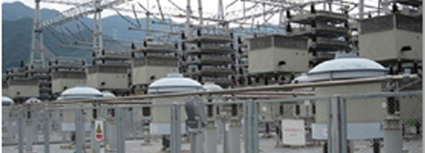
6. Damping reactor:
A damping reactor is connected is series with one or more capacitor banks. It is designed to limit the capacitor switching inrush current while also capable to withstand the rated current and fault current in the event of a short circuit.
7. Test reactor:
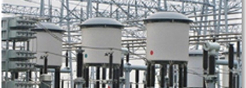
Test reactors are installed in high-voltage and high-power laboratories. The typical applications include: current limiting, synthetic testing of circuit-breakers, inductive energy storage, and simulation circuits.
8. Line trap:
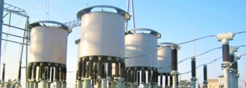
Line traps are connected in series with high voltage and ultra-high voltage ac power lines. They are designed to introduce a high impedance in the carrier frequency range of 40 KHZ to 500 KHZ, with negligible impedance at the power frequency. The high impedance ensures that the carrier signals are not lost or attenuated into the substation.
